Cleaning Method for Petroleum-derived HydrocarbonContained in Waste Water from Parking Lots
Problem
Waste water of parking lots are not influenced by the dispersing effects of fast turning wheels and wind drift. Due to this, they can exhibit levels of HC concentration 50 to 100 times higher than usual street-bound waste water, considering high amounts of traffic and an asphalt layer. Drip loss from the parking vehicles result in the deterioration of the asphalt layer, which increases the contamination with HC even further.
Old Cleaning Method
Coalescence separators can reach outlet concentrations of 5 mg/l HC in laboratory conditions. This excludes the presence of fine particles. In real world situations (with fine particles) they are rendered useless after a short time, as the coalescence webbing dissolves or – in the case of webbing free separators – the fine particles containing HCs are not filtered. Additionally, in order to directly discharge the waste water into a body of water, far lower concentrations are needed (<0,1 mg HC/l).
New, 2 Step Process
Low concentrations of HC of 0.1 mg/l can only be guaranteed by filtration. Filtration is very susceptible to filtration due to high amounts of fine particles and their saturation with hydrocarbons. It is therefore necessary to use a two-step process, contrary to the classic retention soil filter. In the first step, 95% of the fine particles are removed to allow a failure-free operation. This high particle removal in the first step is made possible due to the high specific volume (150-250 m³/ha Au) and the batch operation. Because of the batch operation in the first step, chronologically separate phases of filling, mixing, resting and emptying occur:
- Mixing: Binding of dissolved HC to fine particles
- Rest: Sedimentation of oil saturated particles and floating of free oil
- Removal of floating oil via oil skimmer (possible during 90% of the year) and removal of the sedimentation on a five-year basis
- Removal of the remaining HC contamination with filtration in the second step (soil filter).
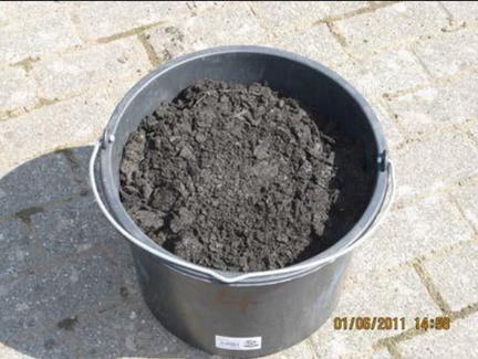
Sediment containing oil in the first step of drainage treatment
The already present RRB of the coalescence separator was used as the volume of the first step. The comparison of amount of sediment from the earlier (picture on left) and current (picture on right) operation, show the effective use of the existing basin volume with batch operation.
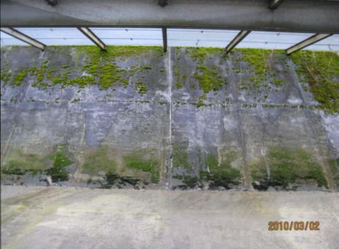 Earlier
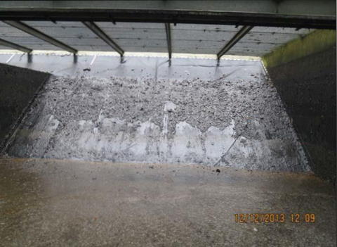 Current
Sediment Dewatering in the First Step
The chronological distribution between the filling and drying phases determines the amount of dry matter in the sediment.
 Sediment, 30% dry matter
 Sediment, 40% dry matter
 Sediment, 55% dry matter
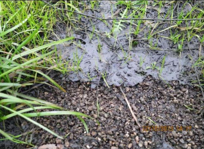
HC Binding Potential in the Second Step
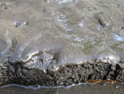
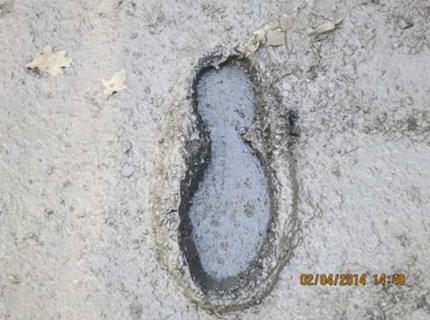
Despite the comparably low concentration of the inlet of the second step (40 mg HC/l to 1.5 mg HC/l) a binding potential for the HC is still. The chromatographic effect during the batch (picture on left) and the HC setting in the vegetation (picture on right) show that the second step also needs a HC binding potential. This is provided by the high HC-mineralization of the fine particles (regeneration of the HC binding potential).
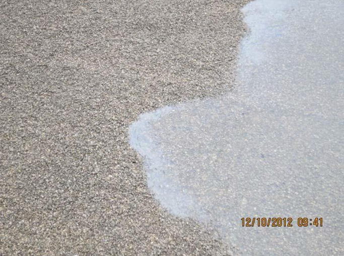 The chromatographic effect during the batch
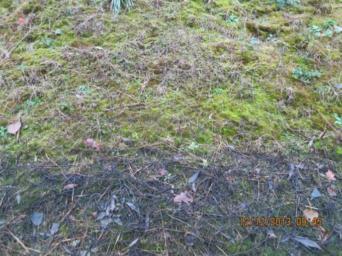 The HC setting in the vegetation
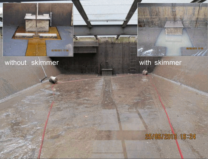
Skimmer operation in the first step of the waste water treatment
The mineral oil, that is not bound to particles with a density higher than 1, is removed from the water’s surface (level: 0- 2.8 m) by the tube skimmer and extracted into a waste oil tank. The impact of the skimmer can be quantified and be seen visually by the absence of an oil layer in the pump well.
Previous experience shows, that the skimmer removes 500 l of water-free oil from the basin. This equates to 35 mg HC per liter of waste water.
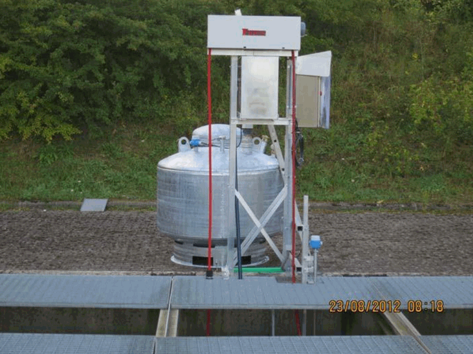
Maintenance of the Oil
The oil removed by the oil skimmer contains large amounts of water (> 90 %). To obtain low-water oil, two separation steps are necessary. The collecting tank of the oil skimmer (picture on left, first separation step) channels the water which accumulates at the bottom of the tank back into the RRB. The waste oil tank (second separation step) has a spigot at the bottom of the tank, to remove the water on a monthly basis at the bottom.
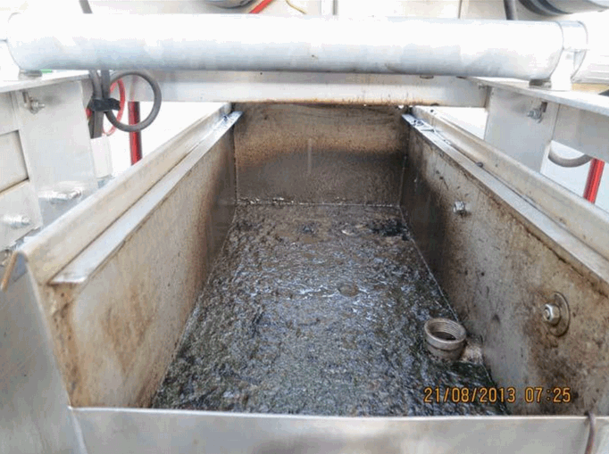 The collecting tank of the oil skimmer (first separation step)
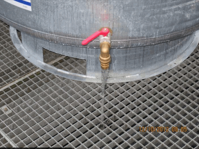 The waste oil tank (second separation step)
Waste Oil Usage
Due to the high mineral oil content, the waste oil and the sediment of the first step have a thermal utilization. The sediment of the second step (filter sediment) can be deposited in the filter for a long time (50 years) due to the low sedimentation rate (0,85 kg TM/m²*a) and very high mineralization rate (> 80 %).
Future Planting of Reed
Despite the very low particle contamination of the filter surface (0,85 kg TM/m²*a), planting of reed is necessary due to the high siltation of the oil saturated particles.
 Filter Surface without Reed
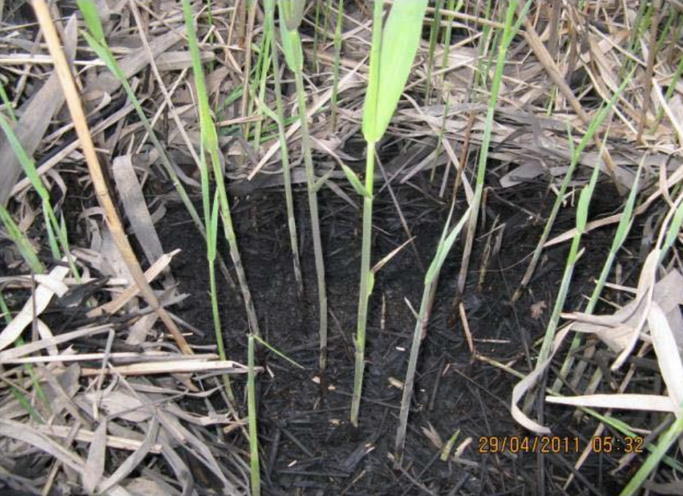 Filter Surface with Reed
Fast Regenration of the Drainage System
The waste water of the parking lot is passed into ditches with a low decline. Despite the high contamination with HC saturated particles (picture on left) after six months of using the new process, an optically better result could be seen (picture on right).
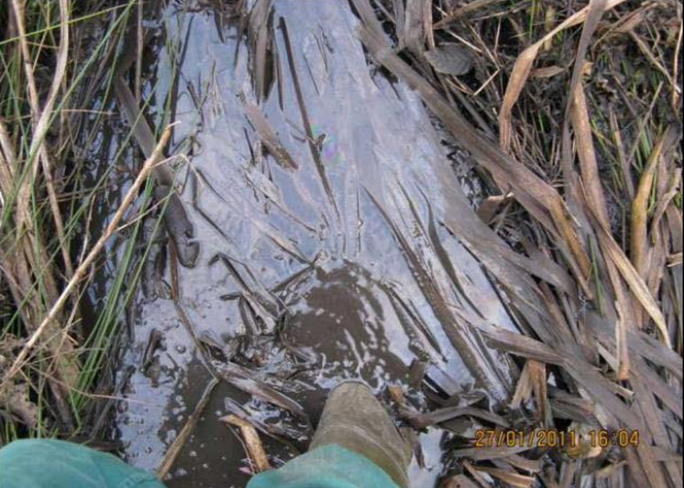 Despite the high contamination with HC
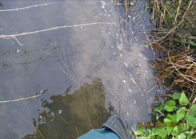 After six months